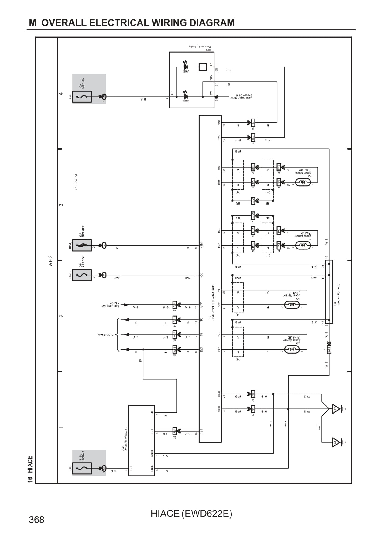
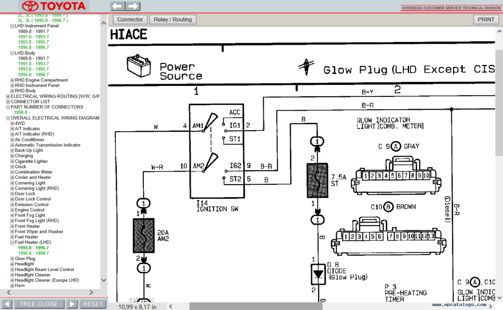
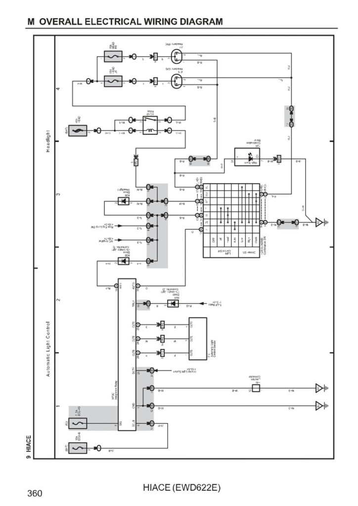
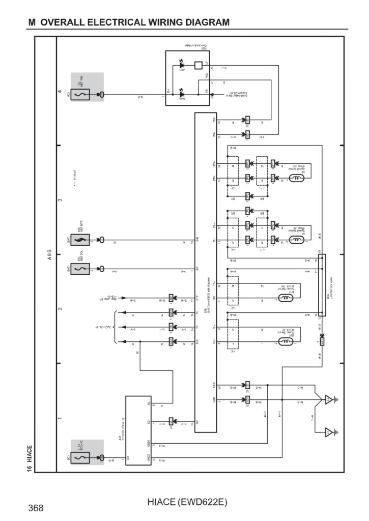
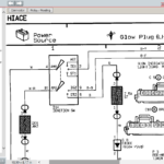
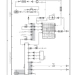
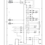
Toyota Hiace Van Electrical Wiring Diagram – The connector program code is utilized to determine whether or not a connector is male or female. The code is also utilized to separate a variety of cable control designs. The male terminal relationship is denoted with the sign (), even though the female and male connector pin amounts are denoted by phone numbers away from rule.
The connections among a variety of pieces are demonstrated through the electrical wiring diagram. A connection code could be .5 or .3 mm, for instance. Furthermore mentioned will be the cable’s colour program code.
The pin numbers of each male and female connections are mentioned by figures on the outside of connector regulations.
The wire and locations routings of any wiring harness are exhibited in the cabling diagram. The very first message in the interconnection code designates where connector is on the diagram. An world stage is additionally integrated on the schematic, which aids in figuring out where connector must be positioned. Along with the planet installation jobs, the cabling diagram will even present the connections and connector numbers that correspond to the same part.
If there is no code, the wiring connector is not linked. A damaged series in addition shows that the two connectors are identical. It’s crucial that you analyze a electrical wiring diagram carefully so that you can right away identify the right connector.
Soil zero
The electric powered connection between a tremendous element along with the the planet is called the soil level. About the Toyota electrical wiring schematic, the earth level code is represented by a note and a number. The amount denotes the soil point’s serial variety, while the message denotes the alphabetical code for your cable control. The ground point program code also displays where the ignition key and cable splice stage are situated.
It helps to understand the different circuits in the car before starting to diagnose an electrical problem. A wires diagram demonstrates the exact electrical wiring of every circuit, which can be divided into numerous circuits for every method inside a car. It is crucial to know how every single circuit functions plus the terrain stage that links it.
prohibit connectors for relays
Around the left side of the car’s tool panel will be the relay block connectors. They join J/B No.3 on the Tool Board Wire (IW). About three figures make up the program code on the relay block connections, each of which stands for the cabling or process. Additionally, it will say if the connector is male or female.
The diagram also displays the hue program code to the communicate prohibit connector. The cable’s colour computer code is displayed in parenthesis within this diagram. Light blue will be the coloration designation for woman connections.
coded shades
Toyota electrical wiring diagrams are colour coded to help make prognosis and troubleshooting easier. The related color codes help you to establish the appropriate link between various automobile components. A cabling funnel for Toyota vehicles includes a number of cords, including positive and negative, soil, and high/low voltage cables. You ought to be aware of the natural/green and white/reddish colored colors within the wiring schematic when studying it because they symbolize the left change transmission along with the braking system lights, respectively.
A Toyota Electrical Wires Diagram with reddish colored arrows signifies that the connections are the proper dimensions. But look out for the yellow arrows. They are certainly not a reliable gauge of your right sizing. They could perplex you.
Toyota electric powered wiring diagram problem solving
Understanding your Toyota’s electric powered wires is essential, especially the colour regulations. Around the world outlined Toyota wires colour codes may well help in a swift diagnosis of power issues. It is crucial to comprehend the wiring diagram’s color codes, because Toyota automobiles feature a large number of sensors and electrical components.
The links between significant ground and components things are displayed on the electrical wiring diagram. The Tool Solar panel Wire is linked to the Generator Space Principal Wire through the “Ch1” connector (female). Around the kept strike solar panel, you will discover a connector. The centre of your back solar panel is where the “H2” soil stage is found. The link involving these spots and the other significant factors is explained with the circuit diagram. Confirm the connections to ensure that every part is linked to the suitable floor.
